What is a printed circuit board -- Basic PCB Concepts?
March 31, 2014This article is from Electrosoft Engineering , it is useful to clarify the mind for new hand.
A printed circuit board or PCB, is a plate or board used for placing the different elements that conform an electrical circuit that contains the electrical interconnections between them.
The most simple printed circuit boards are the ones that contains copper tracks or interconnects only on one of its surfaces. These kinds of boards are known as 1 layer printed circuit board or 1 layer PCB.
The most common PCB's manufactured today are the ones that contain 2 layers, that is, you can find interconnects in both surfaces of the board. However, depending on the physical complexity of the design ( PCB layout ), the boards can be manufactured of 8 or more layers.
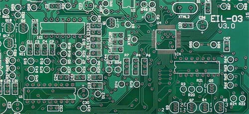
Fig 1. Example region of a 2 layer PCB
Soldermask
For mounting the electrical components on the printed circuit boards, an assembly process is required. This process can be done by hand or through specialized machinery. The assembly process requires the use of solder to place the components on the board. For avoiding or to prevent the solder to accidentally short-circuit two tracks from different nets, pcb manufacturers apply a finish or varnish called soldermask on both surfaces of the board. The most common color of soldermask used in printed circuit boards is green, followed by red and blue.
In EDA software (Electronic design automation), generally exist a rule associated to the expansion of the soldermask. This rule specifies the distance that exists between the pads' borders and the soldermask's border. This concept is illustrated in figure 2 (a).
Silkscreen or Overlay
Silk-screening is the process where the manufacturer prints information on the soldermask conducive to facilitate the processes of assembly, verification and repair. Generally the silkscreen is printed for indicating test points as well the position, orientation and reference of the electronic components that are part of the circuit. Also it can be used for any purpose that the designer may require, for example, the company name, configuration instructions (this was commonly used in old PC motherboards), etc. The silkscreen can be printed on both surfaces of the board. Also the term silkscreen is known as overlay. Figure 2 shows a region of a circuit, all the printings made in white correspond to the silkscreen.
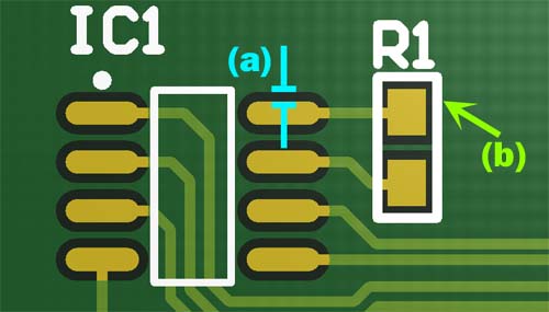
Fig 2. Soldermask expansion (a) and silkscreen (b)
Layer Stackup
As noted before in the beginning of this article, the printed circuit boards can be made of several layers. When a PCB is designed with the aid of an EDA software, often are specified several layers that doesn't necessary correspond to conductive material ( copper ). For example, the silkscreen and soldermask are nonconductive layers. Having conductive and nonconductive layers may lead to confusion, because manufacturers use the term layer when they are referring to the conductive layers only. From now on, we are going to use the term layer without the suffix "CAD" only when referring to conductive layers. If we use the term "CAD Layer" we are referring to all kinds of layer, that is, conductive and nonconductive.
The CAD Layer stackup is the following:
CAD Layer (conductive and nonconductive) |
CAD Layer description |
| 1 | Top silkscreen/overlay ( nonconductive ) |
| 2 | Top soldermask ( nonconductive ) |
| 3 | Top paste mask ( nonconductive ) |
| 4 | Layer 1 ( conductive ) |
| 5 | Sustrate ( nonconductive ) |
| 6 | Layer 2 ( conductive ) |
| ... | ... |
| n-1 | Sustrate ( nonconductive ) |
| n | Layer n ( conductive ) |
| n+1 | Bottom paste mask ( nonconductive ) |
| n+2 | Bottom solder mask ( nonconductive ) |
| n+3 | Bottom silkscreen/overlay ( nonconductive ) |
Figure 3 shows 3 different stackups. The orange color highlights the layers in each stackup. The stackup height, or board thickness can vary depending on the application, however the most used is 1.6 [mm] or 62 [mils]. In some countries [thou] is used as a synonym for [mils]. ( 1 [mil] = 0.001 [inch] = 0.0254 [mm] )
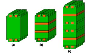
Fig 3. Example of 3 different PCB stackups: 2 layers (a), 4 layers (b) and 6 layers (c)
Component packages
Today in the market you can find a great variety of electronic component packages. It is common to find several types of packages for one device. For example you can find the same integrated circuit in QFP's and LCC's packages.
Basically there exist 3 big families of electronic packages:
| Package | Description | Example Image |
| Thru-Hole |
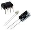
Are all those components that have pins intended to be mounted through a plated hole in the PCB. This kind of component is soldered to the opposite side of the board from which the component was inserted. Generally these components are mounted on one surface of the board only. |
 |
|
SMD/SMT (surface mount device/surface mount technology) |
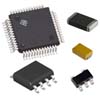
Are all those components that are soldered in the same side of the board from which the component was placed. The advantage of this type of package is that it can be mounted on both sides of the PCB. Also, these components are smaller than the thru-hole type, which allows the design of smaller and denser printed circuit boards. These types of components are useful for frequencies up to 200 [MHz] (fundamental clock frequency). |
 |
| BGA (Ball grid array) |
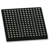
These types of components are frequently used for high density pin integrated circuits. For soldering them to the printed circuit boards it is required to have specialized machinery due that the pins are made of solder balls that have to be melted for making the electrical contact with the pads. BGA components are ideal for high frequency integrated circuits due to the very small parasitic inductances present in the joint between the pad and the balls. These type of components are very common in computer hardware like motherboards and video accelerator cards. |
 |
For more information you can visit this excellent article from wikipedia.
Surface Mount Technology - Wikipedia
Pads
A pad is a small surface of copper in a printed circuit board that allows soldering the component to the board. You can think of a pad as a piece of copper where the pins of the component are mechanically supported and soldered. There are 2 types of pads; thru-hole and smd (surface mount).
Thru-hole pads are intended for introducing the pins of the components, so they can be soldered from the opposite side from which the component was inserted. These types of pads are very similar to a thru-hole via.
The smd pads are intended for surface mount devices, or in other words, for soldering the component on the same surface where it was placed.
Figure 4 depicts 4 components. The components IC1 and R1 have 8 and 2 SMD pads respectively, while both components Q1 and PW have 3 thru-hole pads.

Fig 4. SMD and Thru-hole Pads
Copper tracks
A track is conductive path that is used to connect 2 points in the PCB. For example, for connecting 2 pads or for connecting a pad and a via, or between vias. The tracks can have different widths depending on the currents that flow through them.
It is important to highlight that in high frequencies is necessary to calculate the tracks' width so that the interconnect can be impedance matched along the path created by the track. ( more on this in a future article )
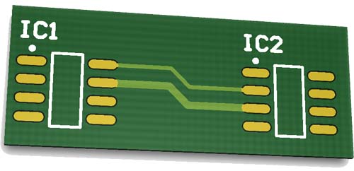
Fig 5. Tracks that interconnect 2 integrated circuits (chips)
Plated Holes (Thru-hole Vias or Full Stack Vias)
When an interconnect must be made from a component that is located on the top layer of the printed circuit board with another that is located at the bottom layer, a via (Vertical Interconnect Access) is used. A via is a plated hole that allows the current to pass through the board. Figure 6 depicts 2 tracks that begin at the pads of a component on the top layer and end at the pads of another component at the bottom layer. For conducting the current from the top layer to the bottom layer, a via is used for each track. The tracks and pads that belong to the bottom layer are visually dimmed, so you can differentiate them from the ones that are on the top layer.
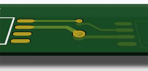
Fig 6. Two integrated circuits located on opposite sides of the PCB are connected using thru-hole vias
Figure 7 depicts a more detailed view of a transversal section of a 4 layer printed circuit board or 4 layer PCB. The colors that appear in the Figure are explained in the following table:
| Color | Legend for Figure 7 |
| green | Top and bottom soldermasks |
| red | Top layer ( conductive ) |
| violet | Second layer. In this case this layer is used as a power plane ( i.e. Vcc or Gnd ) |
| yellow | Third layer. In this case this layer is used as a power plane ( i.e. Vcc or Gnd ) |
| blue | Bottom Layer ( conductive ) |
The PCB depicted in figure 7 shows a track that belongs to the top layer that goes through the board using a thru-hole via, and then continues as a track that belongs to the bottom layer.
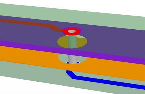
Fig 7. Track from the top layer going through the PCB and ending on the bottom layer
Blind vias
In high density complex designs is necessary to use more than 2 layer as we have shown in figure 7. Generally in multilayer system designs where there are many integrated circuits, power planes ( Vcc or gnd) are used to avoid excessive routing for power rails. In other words, it is lot easier and more secure to directly connect to the power planes that are beneath the chips instead of routing long tracks for the PDS ( Power Delivery System ) ( this can also be achieved with thru-hole vias ). Also there are times that a signal track must be routed from an external layer ( top or bottom ) to an internal layer with minimum via height because it can act as a stub and maybe produce an impedance mismatch. This can cause reflections and produce signal integrity issues ( more on this in a future article ). For these kinds of interconnects blind vias are used, which allows a connection to be made from an external layer to an internal layer with minimum via height. A blind via starts on an external layer and ends on an internal layer, that's why it has the prefix "blind".
To know if a certain via is blind, you can put the PCB against a source of light and see if you can see the light coming from the source through the via. If you can see the light, then the via is thru-hole, otherwise the via is blind.
It is very useful to use these kinds of vias in printed circuit board design when you don't have too much space for placing components and routing. You can put components on both sides and maximize the space. If the vias were thru-hole instead of blind, there would be some extra space used by the vias on both sides.
Figure 8 depicts 3 vias that are part of 4 layer printed circuit board. If we see the picture from left to right, the first via that we will see is thru-hole via or fullstack via. The second via begins at the top layer and ends at the second layer ( inner ), so we say that this is a 1-2 blind via. At last, the third via begins at the bottom layer and ends at the third layer, so we say that this is a 3-4 blind via.
It is important to have in mind that blind vias are often manufactured in consecutive layers, in other words between L1 L2, L3 L4, Ln-1 Ln.
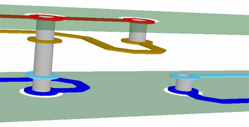
Fig 8. Comparison between a Thru-hole and a Blind via
The disadvantage of this type of via is its high price when compared to the thru-hole alternative.
Buried Vias
These vias are similar to the blind ones, with the difference that they begin and end on an inner layer. If we look at the image depicted in figure 9 from left to right, we see that the first one is a thru-hole or full stack via. The second one is a 1-2 blind via, and the last one is a 2-3 buried via that begins on the second layer and ends on the third layer.
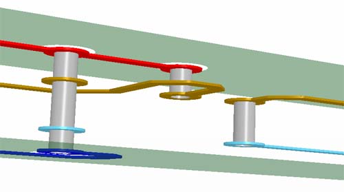
Fig 9. Comparison between Thru-hole vias, Blind vias and Buried vias
It is important to have in mind that blind vias are often manufactured in consecutive layers (i.e. L1 L2)
As the case of blind vias, the main disadvantage of this type of via is its high price when compared to the thru-hole alternative. Using b/bb vias may impact the cost of the boards in an important way, so you decide if it's better to use these kinds of vias or use bigger boards with thru-hole type vias.
Eng. M. Patricio Cohen
Electrosoft Engineering


